3D Printed Prototypes – Broken Promises?


3D Printed Prototypes – Broken Promises?
Understanding the weaknesses uncovers the strengths
By Dan Uhler, product development engineer
FDM, SLA, SLS, MJF, DLP... the 3D printing industry loves its acronyms. Each one represents different 3D printing technologies, but the one I’ll focus on is FDM, or Fused Deposition Modeling.
This technology, in an oversimplified form, is a hot glue gun filled with plastic and mounted to a 3-axis machine. There are myriad FDM options on the market for every level of 3D printer user.
A hobbyist can purchase an FDM machine for about $200 as of this writing. In our product development lab, we like to have something a little more robust that requires less tinkering and allows us to focus on the product designs.
3D printing is immensely useful to us because of its ability to verify designs and get innovative parts out the door in a time- and cost-effective manner.
The hitch
Surely, something this good must carry some form of curse. Well yes, but it’s one we can live with. FDM parts, unlike some other 3D printing technologies, have anisotropic material properties. Their strength is weaker in one direction. This differs from isotropic material, which has the same strength in every direction.
A good comparison is wood. It’s an anisotropic material, which is why it’s easier to split along the grain

Figure 1: This log can be easily split down the middle with a wedge or axe because of its anisotropic material properties.
Figure 2: If I tried to split this log from the side, I would have a much more difficult time getting through the wood.
Why do FDM parts have anisotropic material properties?
In order to understand where the anisotropic material properties of FDM prints comes from, let’s take a step back and look at thermoplastic polymers. Plastics engineers often use the analogy of a bowl of spaghetti when describing their molecular structure. Each noodle is like an individual microscopic polymer chain making up the plastic material, and the longer and more woven together those "noodles" are, the stronger the material will be.
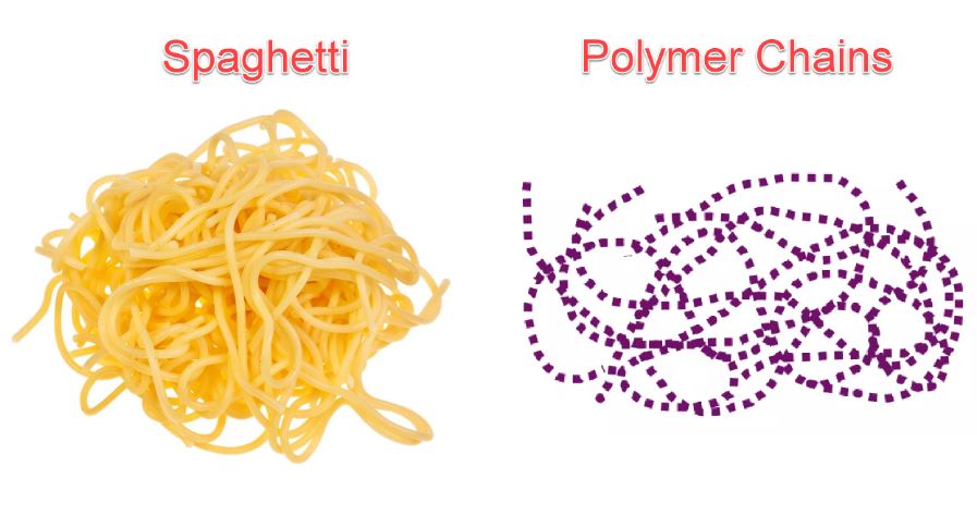
Figure 3: Left image from https://phantomplastics.com/plastic-materials-training/introduction-to-plastic-materials/
Right image from SPE webinar Dynamic Mechanical Analysis, Jeff Jansen, Senior Managing Engineer and Partner, The Madison Group, June 2019
When a material, PLA for example, is extruded from the nozzle of an FDM printer, the plastic is a piping hot 200 degrees F. This is hot enough to keep the PLA melted and allows all those spaghetti noodles to entangle with one another, which is what we want to give plastic its strength.
That’s fine for the first layer of my 3D printed part, but I have 299 more layers to go, and the layer that has already been printed cannot stay melted because it needs to stay in the shape of my part. Now that my first layer has cooled slightly, the polymer molecules are not going to be able to entangle with the next layer of molten plastic nearly as well.
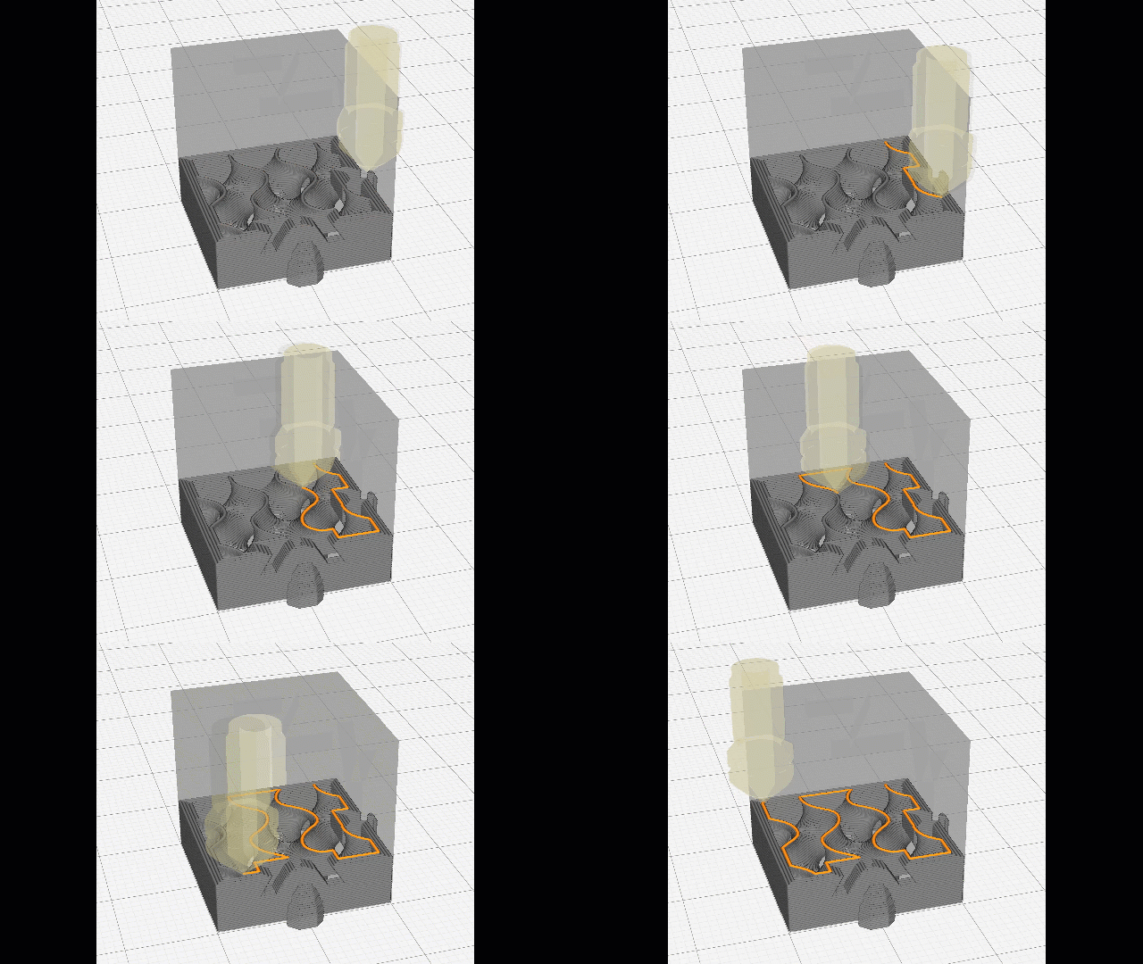
Figure 4: FDM nozzle printing the next layer (orange) of a 3D printed part.
Imagine the bowl of spaghetti again. If we try to push two handfuls of spaghetti together, the noodles are not going to entangle with each other as well as each individual handful of spaghetti already is. This is where the anisotropic material properties come from and why FDM print orientation is critical to create effective parts. If you are playing along at home, you can put the spaghetti away and wash your hands now.
Seems like a big drawback, so why not use another printing process?
The speed, cost effectiveness and simplicity of desktop FDM printers is unparalleled in the current 3D printing landscape. I often need to have a part in my hand today due to a last-minute change or a tight deadline. Desktop FDM machines will deliver quickly if I understand and minimize their weaknesses.
Here’s an example. The connector clip is a common feature on many of our parts. It frequently needs to be prototyped with 3D prints for an initial fit check. This connector clip needs to flex for the part to be installed correctly and for the fit check to serve its purpose.
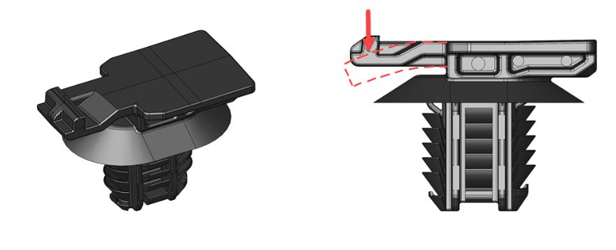
Figure 5: Connector clip. Dashed red line shows the flexing direction of the connector clip arm.
A bad 3D print setup will result in the connector clip breaking during installation. But a little due diligence to print it correctly lets us complete the fit check in one day and ensure we get production parts delivered on time.
Figure 6 shows the layer lines created during the 3D printing process in two different orientations. The left orientation shows how flexing the arm will “peel” the layers apart. On the right, the layers run perpendicular to the flex, so the printed part will function appropriately.
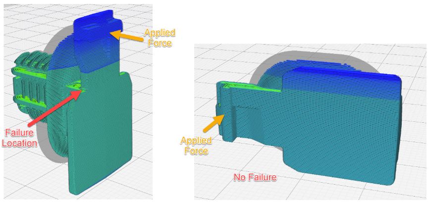
Figure 6: Left image shows a poor print orientation for this part made using FDM, while right image shows correct orientation.
Understanding where the anisotropic material properties of FDM parts come from allows us to minimize the effect of their weakness while taking full advantage of the strengths.
Any great ah-ha moments you’ve come across for prototyping with 3D printing?

About the Author:
Dan Uhler works as a product development engineer for the general market group at HellermannTyton. He joined our team in 2017 when he moved from Madison to Milwaukee. Dan has a bachelor's degree in engineering mechanics from the University of Wisconsin - Madison. He is a member of both SAE and SPE and has a strong professional interest in additive manufacturing and finite element analysis. Outside the office, Dan enjoys cooking, exercise, and, despite being an Illinois import, is a Packers fan..


